The IBM System/360 was a groundbreaking family of mainframe computers announced on April 7, 1964.
Designing the System/360 was an extremely risky “bet-the-company” project for IBM, costing over $5 billion.
Although the project ran into severe problems, especially with the software, it
was a huge success, one of the top three business accomplishments of all time.
System/360 set the direction of the computer industry for decades and popularized features such as the byte, 32-bit words, microcode, and standardized interfaces.
The S/360 architecture was so successful that it is still supported by IBM’s latest z/Architecture mainframes, 55 years later.
Prior to the System/360, IBM (like most computer manufacturers) produced multiple computers with entirely incompatible architectures.
The System/360, on the other hand, was a complete line of computers sharing a single architecture.
The fastest model in the original lineup was 50 times as powerful as the slowest,1 but they could all run the same software.2
The general-purpose System/360 handled business and scientific applications and its name
symbolized “360 degrees to cover the entire circle of possible uses.”34

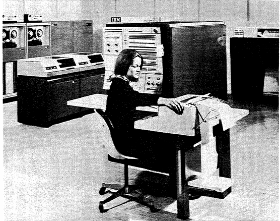
Large computer room with an IBM System/360 Model 85. The CPU, the double-H unit in the center, weighed over 7 tons.
Cabinets in front are core memory storage, holding 256 kilobytes each.
Cabinets on the right are I/O channels, connected to I/O devices at the back:
tape drives, printers, disk drives, and card readers. Photo from IBM.
Although the S/360 models shared a common architecture, internally they were completely different to support the wide range of
cost and performance levels.
Low-end models used simple hardware and an 8-bit datapath while
advanced models used features such as wide datapaths, fast semiconductor registers, out-of-order instruction execution, and caches.
These differences were reflected in the distinctive front panels of these computers, covered with lights and switches.
This article describes the various S/360 models and how to identify them from the front panels.
I’ll start with the Model 30, a popular low-end system, and then go through the remaining models in order.
Conveniently IBM assigned model numbers rationally, with the size and performance increasing with the model number, from the stripped-down but popular Model 20 to the high-performance Model 195.
IBM System/360 Model 30
The photo below shows a Model 30, one of the lower-end S/360 machines, with
8 to 64 kilobytes of magnetic core memory.
The CPU cabinet was 5 feet high, 2’6″ wide and 5’8″ deep and weighed 1700 pounds,
enormous by modern standards but a smaller computer for the time.
System/360 computers were built from fingernail-sized modules called Solid Logic Technology (SLT) that contained a few transistors and resistors, not as dense as integrated circuits.
Although the Model 30 was the least powerful model when the System/360 line was announced,
it was very popular and profitable,
renting for $8,000 a month and
bringing IBM over a billion dollars in revenue by 1972.

IBM S/360 Model 30 on display at the Computer History Museum.
You might wonder why these computers had such complex consoles.5
There were three main uses for the console.6
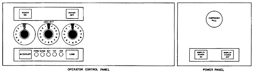
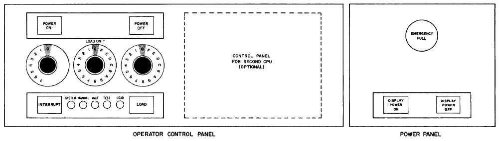
The first use was basic “operator control” tasks such as turning the system on, booting it, or powering it off, using the controls shown below.
These controls were consistent across the S/360 line and were usually the only controls the operator needed.
The three hexadecimal dials selected the I/O unit that held the boot software.7
Once the system had booted, the operator generally typed commands into the system rather than using the console.
. The buttons provided \"Power On\", \"Power Off\", \"Interrupt\", and \"Load\", while the lights indicated if the system was running.")
The “operator control” section of the control panel was used for basic tasks such as booting the system (called Initial Program Load or IPL). The buttons provided “Power On”, “Power Off”, “Interrupt”, and “Load”, while the lights indicated if the system was running.
The second console function was “operator intervention”: program debugging tasks such as examining and modifying memory or registers
and setting breakpoints.
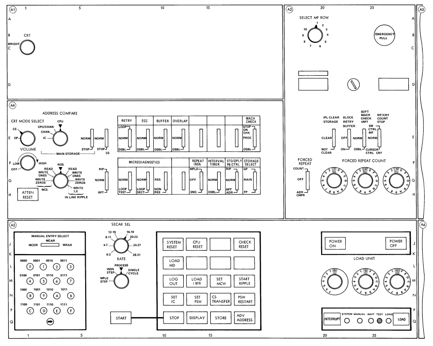
The Model 30 console controls below were used for operator intervention.
To display memory contents, the operator selected an address with the four hexadecimal dials on the left and pushed the Display button,
displaying data on the lights above the dials.
To modify memory, the operator entered a byte using the two hex dials on the far right and pushed the Store
button. (Although the Model 30 had a 32-bit architecture, it operated on one byte at a time, trading off speed for lower cost.)
The Address Compare knob in the upper right set a breakpoint.

The lower part of the Model 30 console was used for operator intervention. Note the binary-to-hexadecimal conversion chart below the hexadecimal dials.
The third console function was supporting system maintenance and repair performed by an IBM customer engineer.
The customer engineering displays took up most of the console and provided detailed access to the computer’s complex internal state.
On the Model 30 console above, the larger middle knob (Display Store Selection) selected any of the internal registers for display or
modification.
The rows of lights below showed the microcode instruction being executed from “read only storage” and operations on the I/O channel.
 and I/O channel. These registers were used internally and were not visible to the programmer.")
Closeup of the IBM S/360 Model 30 console showing indicators for the microcode (read only storage) and I/O channel. These registers were used internally and were not visible to the programmer.
The consoles also included odometer-style usage meters, below the Emergency Power Off knob.10
The standard IBM rental price covered a 40-hour week and a customer would be billed extra for excess usage.
However, customers were not charged for computer time during maintenance. When repairing the system, the customer engineer turned the keyswitch, causing time to be recorded on the lower service meter instead of the customer usage meter.

The Emergency Power Off knob shut down the entire system. Below it were the usage meters. The keyswitch selected the maintenance meter, so customers would not be charged for computer operation during maintenance.
IBM System/360 Model 20
Moving now to the bottom of the S/360 line, the
Model 20 was intended for business applications.9
Its storage was limited, just 4K to 32K bytes of core storage, and it was extremely
slow even by 1960s standards, performing about 5700 additions per second.
This slow CPU was enough to generate business reports from punch cards since the card reader only read 8 cards per second.
To reduce its price, the Model 20 implemented a subset of the S/360 instructions and used half-sized registers,8 making it incompatible with the rest of the S/360 line.
Despite its limitations, the Model 20 was the most popular S/360 model due to its low price, with more than 7,400 Model 20s in operation by the end of 1970.
The monthly rental price of the Model 20 started at $1280 with the purchase price starting at $62,710.

Waelder,
CC BY-SA 2.5.
The Model 20’s small console (above) allowed the operator
to turn the computer on and off, load a program, and so forth.
A few rows of lights showed the contents of the computer’s registers and
hexadecimal dials loaded a byte (left two dials) into a memory address (next four dials).
Another dial let the operator debug a program by modifying memory, setting a breakpoint, or single-stepping through a program.
The Emergency Power Off knob and usage meters are at the far right.
The Model 20 hid a separate control panel for customer engineers behind a cover (below).
This panel provided additional controls and lights for diagnostics and access to the microcode.
Because the Model 20 was simpler internally than the Model 30, not as much information needed to be displayed
to the customer engineer.

IBM System/360 Model 22
The Model 22 was a cut-down version of the Model 30 at 1/3 the price, providing about 5 times the performance of the Model 20.
It was the last S/360 computer introduced, announced in 1971.
IBM said the Model 22 “combined intermediate-scale data processing capability with small-system economy.”
A base Model 22 CPU rented
for
$850 a month
(less than the Model 25 or most Model 20s) with a purchase price of $32,000 to $44,000. A typical configuration
with three disk drives, line printer and card reader cost considerably more, renting for about $5,600 or purchased for $246,000.
The processing unit weighed 1500 pounds and was about the size of two refrigerators.11
Unlike the Model 20, the Model 22 was compatible with the rest of the S/360 line.

IBM.
The Model 22’s console was very similar to the Model 30’s, since the Model 20 was derived from the Model 30.
The Model 22 had fewer rows of lights, though, and the bulbs projected from the console in individual holders,
rather than being hidden behind the Model 30’s flat overlay.
Because of its late introduction date, the Model 22 used semiconductor memory rather than magnetic core memory.
IBM System/360 Model 25
The Model 25 was another low-end system, designed to be less expensive than the Model 30 but without the incompatibility of the Model 20.
A typical Model 25 rented for $5,330 a month with a purchase price of $253,000.
It was introduced in 1968, late in the S/360 line but before the Model 22.
It was a compact system, packaging
I/O controllers in the main cabinet (unlike other S/360 systems).
Unlike other low-end systems, it had a two-byte datapath for higher performance.
One of the Model 25’s features was a smaller easy-to-use console; on the Model 25, many operations used the console typewriter rather than the control panel.
In the picture below, note the squat control panel, about 2/3 the height of the black computer cabinet behind it.
The control panel reused dials for multiple functions (such as address and data), making it more compact than the Model 30 panel.

IBM.
IBM System/360 Model 40
The Model 40 was a popular midrange model, more powerful than the Model 30.
It
typically
rented for about $9,000-$17,000 per month and
brought IBM over a billion dollars in revenue by 1972.
For improved performance, the Model 40 used a two-byte datapath (unlike the Model 30, which handled data one byte at a time)

Daderot.
In the photo above, you can see that the Model 40 console is considerably more complex than the Model 30 console, reflecting the increased internal complexity of the system.
Like the other models, it had three hex dials in the lower right to boot the system.
But instead of hex dials for address and data entry, the Model 40 had rows of toggle switches: one for the address and one for the data.
To keep the number of lights manageable, the Model 40 used
two “rollers” that allowed each row of lights to display eight different functions.
Each roller had an 8-position knob on the right side of the console, allowing a particular register or display to be selected.
The knob physically rotated the legend above the lights to show the meaning of each light for the selected function.

Multi-function rollers on the S/360 Model 40 allowed more data to be displayed on the console.
IBM System/360 Model 44
IBM’s competitors in the scientific computing market offered cheaper but faster systems designed specifically for numerical computing.
IBM created the Model 44 to address this gap, giving it faster floating point and data acquisition instructions while
dropping business-oriented instructions (decimal arithmetic and variable field length instructions).3
These changes made the Model 44 somewhat incompatible with the rest of the S/360 line,
but it was 30 to 60 percent faster than the more-expensive Model 50 on suitable workloads.
Despite the improved performance, the Model 44 met with limited customer success.

IBM System/360 Model 44 control panel.
The Model 44’s console was superficially similar to the Model 40’s, with toggle switches and two roller knobs,
but on the Model 44, one of the rollers changed the function of the toggle switches.
The two models were entirely different internally; for higher performance, the Model 44 used a hard-wired control system instead of microcode.
It also used a four-byte datapath, moving data twice as fast as the Model 40,
so it has had twice as many lights and switches in each row on the console (32 data bits + 4 parity bits).12
One unusual feature of the Model 44’s console was a rotary knob (bottom knob on the left) to select floating point precision; reducing the precision increased speed.
Another feature unique to the Model 44 was a disk drive built into the side of the computer. The removable disk cartridge held about 1 megabyte of data.
The buttons in the lower left of the console controlled the disk drive.

IBM System/360 Model 50
The Model 50 had significantly higher performance than the Model 40, partly because it
used a four-byte datapath for higher performance.
Physically, the Model 50 was considerably larger than the lower models: the CPU with 512 KB of memory was 5 large frames weighing over 3 tons.
The Model 50
typically
rented for about $18,000 – $32,000 per month.
It could be expanded with 8 more megabytes externally;
each IBM 2361 “Large Capacity Storage” unit held 2 megabytes of core memory and weighed a ton.

Sandstein,
CC BY-SA 3.0
The Model 50’s console was more complex than the Model 40 or Model 44. Like the Model 44, the toggle switches and lights are 32 bits + parity because of the 4-byte datapath.
The Model 50 used four roller knobs to support multiple functions on each row of lights.
The voltmeter and voltage control knobs in the upper left were used by an IBM customer engineer for “marginal checking”.
By raising and lowering the voltage levels about 5% and checking for failures, borderline components could be detected and replaced before they caused problems.

Control panel of the IBM System/360 Model 50. This panel has marginal check controls for auxiliary storage in the upper right, replacing the dataflow diagram.
IBM System/360 Models 60, 62, 65 and 67
The models in the 60 series were very similar, designed for large scale business and scientific computation.
Models 60 and 62 were announced at the S/360 launch, but they were never shipped. Competitors announced faster machines so IBM improved the core memory to create the
Model 65; it had fast .75μs memory, obsoleting the Model 60 (2μs) and Model 62 (1μs) before they shipped.
The Model 65 typically rented
for $50,000 a month.

The Model 65’s console had much in common with the Model 50, although it had 6 rollers instead of 4 to display more information.
The Model 60 and higher models used an eight-byte datapath and storage interleaving for highest memory performance.13
To support the wide datapath, the console had two rows of toggle switches for data, as well as
more address toggle switches to support the larger address range.
Each roller controlled 36 lights (4 bytes + parity), so the 64-bit registers were split across two rows of lights.

The Model 67 was announced in 1965 and shipped in 1966 to
support the demand for time-sharing systems, computers that could support numerous users at the same time.
(Most computers back then were “batch” systems, running a single program at a time.)
The Model 67 was essentially a Model 65 with the addition of
virtual memory, called Dynamic Address Translation.
It supported “on-line” computing with remote users, time-sharing, and multiple concurrent users.
Unfortunately, due to delays in releasing the operating system the Model 67 was not a large success, with only 52 installations by the end of 1970.
The 60-series models were physically large, especially with multiple memory units attached.
They could also be configured as a two-processor “duplex” multiprocessor, weighing over four tons and occupying about 400 square feet; note the two consoles in the photo below.

IBM System/360 Models 70 and 75
The high-end Model 70 was announced in April 1964, but as with the Model 60, improvements in memory speed caused the Model 70 to be replaced
by the faster Model 75 before it shipped.
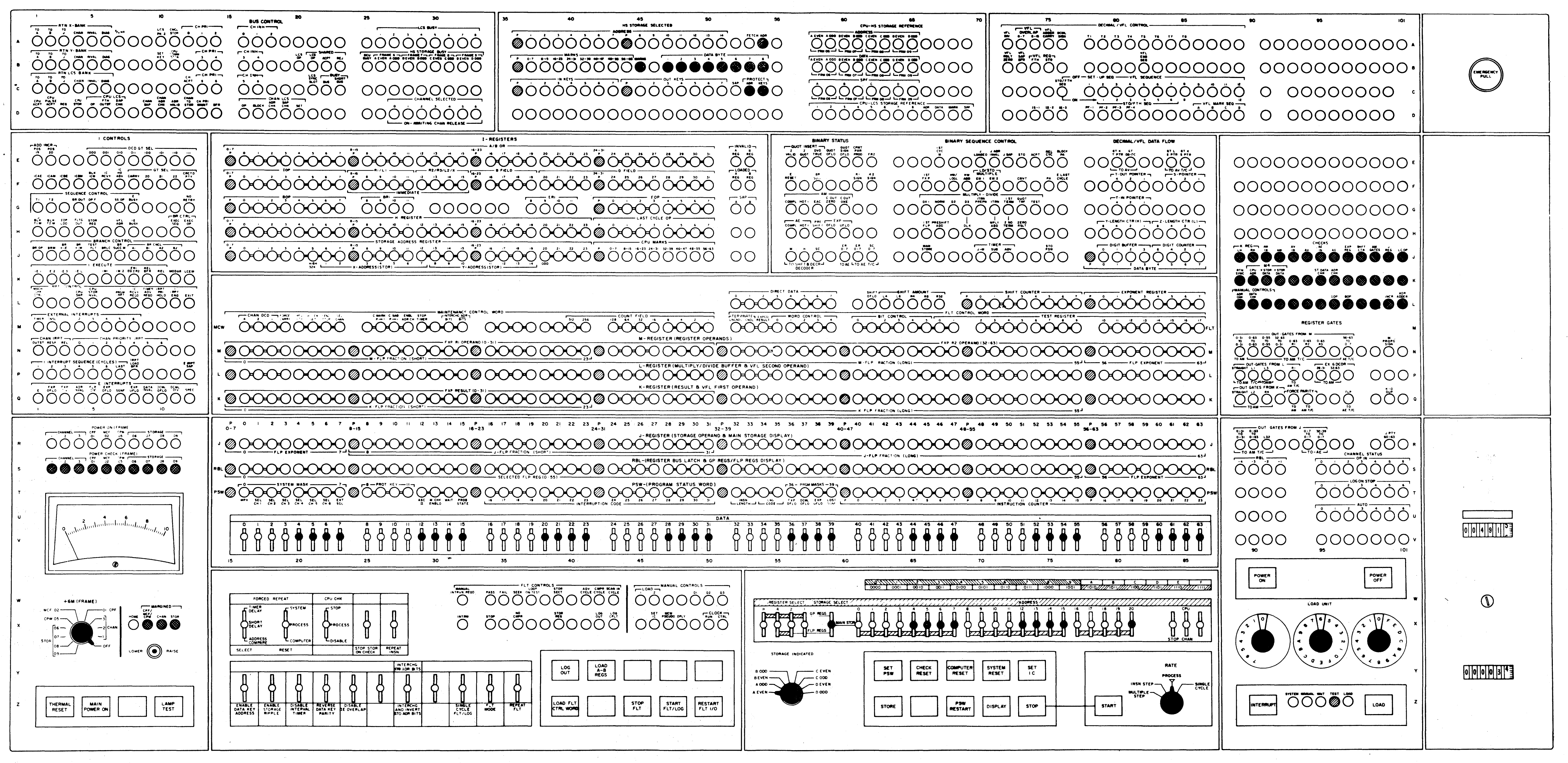
The Model 75’s console was much larger than the lower models with a remarkable number of lights, for two reasons.14
First,
the Model 75’s internal architecture was complex, with multiple data paths and internal registers
to improve performance, resulting in more data to display.
Second, instead of using rollers to display different functions, the Model 75 displayed everything at once on its vast array of lights.

Model 75 Functional Characteristics page 4.
I’ll point out some of the highlights of the console.
The standard operator dials to boot the system were in the lower right (section N), next to the usage meters (P).
To examine and modify memory, the operator used the address switches (R), 64 data switches (M), and lights (M).
Most of the other sections were for customer engineers. The voltmeter (K) was used for marginal checking.
Other sections included bus control (A), high-speed storage (B), variable field length instructions (C),
instruction controls (E), and registers (F, L).
<!–

–>

The Model 75 had a monthly rental price of $50,000 to $80,000 and a purchase price from $2.2 million to $3.5 million.
IBM considered the Model 75 a 1-MIPS computer, executing about 1 Million Instructions Per Second.
(This would put its performance a bit below an Intel 80286, or about 1/10,000 the performance of a modern Intel Core I7.)
IBM System/360 Model 85
The high-end Model 85 was a later model in the S/360 line, introduced in 1968.
Its massive processing unit consisted of a dozen frames and weighed about 7 tons, as shown in the photo at the beginning of the article.
A key innovation of the Model 85 was the memory cache to speed up memory accesses.
While caches are ubiquitous in modern computers,
the Model 85 was the first commercial computer with a main-memory cache.
The Model 85 was also IBM’s first computer to use integrated circuits (which IBM called
Monolithic System Technology or MST).
Unfortunately, the Model 85 was not a success with customers; its price was relatively high
at a time when the data processing industry was going through a slowdown.
As a result, only about 30 Model 85 systems were ever built.
The Model 85 used a radically different approach for the console.15
The control panel of lights and switches was small compared to other S/360 systems.
Instead, a CRT display and keyboard were used for many operator functions,
visible in front of the operator below.
To the left of the operator, an “indicator viewer” replaced most of the panel lights.
The indicator viewer combined 240 lights with a microfiche projector that displayed the appropriate labels for ten different configurations, a more advanced version of the rollers that provided the equivalent of 2400 individual lights.
The system also included a microfiche document viewer (far left of photo), replacing binders of maintenance documentation with compact microfiche cards.
.")
source).
IBM System/360 Models 90, 91, 92 and 95
The Model 90 was just a footnote in the original S/360 announcement, a conceptual “super computer”.
The improved Model 92 was announced a few months later but then scaled back to create the Model 91.
The Model 91 was intended to compete with the CDC 6600 supercomputer (designed by Cray), but
ended up shipping in 1967, about two years after the CDC 6600.16
As a result, the Model 91 was rather unsuccessful with only 15 to 20 Model 91’s produced, despite cuts to the $6,000,000 price tag.
In comparison, CDC built more than 200 computers in the 6000 series.
The Model 91 was architecturally advanced; it was highly pipelined with out-of-order execution and multiple functional units.
Reflecting its complex architecture, the Model 91 had a massive control panel filled with lights and switches.
The lower part of the main panel had the “operator intervention” functions, including toggle switches for a 24-bit address and 8 bytes of data.
The remainder of the lights showed detailed system status for IBM customer engineers.
The basic operator controls (power, boot) were not on the main panel, but on a
small panel
below and to the right of the main console. (It is visible in the photo below, just to the left of the operator’s head.)
The operator also used the CRT for many tasks.15

Console of the IBM System/360 Model 91. The very large computer itself is not visible in this photo. Photo source unknown.
The Model 91 was a room-filling system as the central processor consisted of seven stand-alone units: the CPU itself, three power supplies (not counting the motor-generator set), a power distribution unit, a coolant distribution unit, and a system console. In addition, an installation had the usual storage control unit, I/O channel boxes, and I/O devices.
The Model 91 was the first IBM system to use semiconductor memory, in its small “storage protect” memory but not the main memory.
As for the Model 95, IBM started researching thin-film storage as a replacement for core memory in 1951.
After years of difficulty, in 1968 IBM shipped thin-film memory in the Model 95 (which was otherwise the same as the Model 91).
Although this was the fastest megabyte memory for many years,
IBM sold just two Model 95 computers (to NASA) and then abandoned thin-film memory.
IBM System/360 Model 195
The Model 195 was “designed for ultrahigh-speed, large-scale computer applications.”
It was a reimplementation of the Model 91 using integrated circuits (called “monolithic circuitry”, still in IBM’s SLT-style packages),
and also included a
32K byte memory cache.
It rented for $165,000 to $275,000 a month, with purchase prices from $7 million to $12.5 million.
The Model 195’s performance was comparable to the CDC 7600 supercomputer,
but as with the Model 91, the Model 195 was delivered about two years later than the comparable CDC machine, limiting sales.
The Model 195’s console (below) was very similar to the Model 95’s.
As with the Model 91, the Model 195 used a CRT15 for many operator tasks and had a separate small operator console (not shown).
17

This console has the dark color scheme used for S/370 consoles even though it was an S/360 system.
With approximately 2000 light bulbs, the console has complex wiring, visible below the console.
Photo from
Science Museum Group.
It can be hard to distinguish the consoles of the common Models 30, 40, 50 and 65.
The diagram below shows the main features that separate these consoles, helping to identify them in photographs.
The Model 30 had a flat silkscreened panel without individual indicators and toggle switches. It can also be distinguished
by the 9 dials at the bottom, and the group of four dials on the right.
The Model 40 had two rollers, and the group of four dials on the left.
The Model 50 had four rollers, and a voltmeter next to a dozen knobs.
The Model 60 had six rollers, and a voltmeter with just a couple knobs.
 provides a convenient way to tell the models apart.")
Common IBM System/360 consoles, with distinguishing features identified. The number of roller knobs on the right (0, 2, 4, or 6) provides a convenient way to tell the models apart.
By modern standards the System/360 computers were unimpressive: the Model 20 was much slower and had less memory than the
VIC-20 home computer (1980), while at the top of the line, the Model 195 was comparable to a Macintosh IIFX (1990), with about 1/1000 the compute power of an iPhone X.
On the other hand, these mainframes could handle a room full of I/O devices and dozens of
simultaneous users.
Even with their low performance, they were running large companies, planning the mission to the Moon, and managing the nation’s air
traffic control.
Mainframe computers aren’t thought about much nowadays, but they are still used more than you might expect; 92 of the top 100 banks use mainframes, for instance. Mainframe sales are still a billion-dollar market, and IBM continues to release new mainframes in its Z series.
Although these are modern 64-bit processors, amazingly they are still backward-compatible with the System/360 and customers can still run their 1964 programs.
Thus, the S/360 architecture lives on, 55 years later, making it probably the longest-lasting computer architecture.
I announce my latest blog posts on Twitter, so follow me @kenshirriff for future articles. I also have an RSS feed.
The book IBM’s 360 and Early 370 Systems describes the history of the S/360 in great detail.
IBM lists data on each model, including dates, data flow width, cycle time, storage, and microcode size. Another list with model details is here.
Diagrams of S/360 consoles are at quadibloc.
The article System/360 and Beyond has lots of info.
A list of 360 models and brief descriptions is here.
Here are some links for each specific model:
Model 20: Functional Characteristics manual,
Field Engineering manuals,
Wikipedia.
Model 22: Wikipedia,
IBM.
Model 25: Functional Characteristics manual,
Wikipedia,
Field Engineering manuals.
Model 30: Functional Characteristics manual,
Wikipedia,
Field Engineering manuals,
photos
here,
here,
here,
here,
here.
Model 40: Functional Characteristics manual,
Field Engineering manuals,
Wikipedia.
Other photos
here
(from IBM System/360 System Summary page 6-7),
here,
here.
The photo here apparently shows a prototype console with a roller.
Model 44: Functional Characteristics manual,
Wikipedia, brochure.
The photo here shows an earlier prototype with a different console.
Some interesting notes are here.
Model 50: Functional Characteristics manual,
Field Engineering manuals,
Wikipedia,
photos here and
here,
CuriousMarc video.
Model 65: Functional Characteristics manual,
Field Engineering manuals,
Wikipedia,
photo here.
Model 67: Functional Characteristics manual,
Wikipedia,
photos here,
here.
Model 75: Functional Characteristics manual,
Field Engineering manuals
(console diagram),
Wikipedia.
Model 85: Functional Characteristics manual
(console diagram, page 20),
Wikipedia.
Model 91:
Functional Characteristics manual,
Wikipedia.
Other photos here, here here
here and
here.
Model 92:
IBM info with photo.
Model 195:
Functional Characteristics and
Wikipedia,
photo here.

_console_-_Computer_History_Museum_(2007-11-10_23.06.26_by_Carlo_Nardone).jpg)